
In today’s modern age of CAD models and CAM programming, one could assume that we’ve moved beyond the times when part prints and CNC drawings were commonplace in manufacturing. After all, there is a great deal of information that can be pulled from a 3D model, so there really isn’t a need for prints anymore, right?
Wrong! While 3D design has been a boon to the industry and is a valuable tool for engineers and machinists alike, the value of a detailed CNC drawing cannot be understated. Below, we will discuss some tips for producing a thorough drawing and how it can be used to save time and avoid headaches in the manufacturing process.
Provide Various Views
Clarity is key. When designing a drawing, engineers should include multiple views that highlight key part features/components and avoid unnecessary “guesswork” by anyone trying to interpret part geometry.
Axonometric Views
This should be a clean representation of the finished part. It is generally angled in such a way as to showcase as many part features as possible. This view is generally portrayed without dimensions so as not to detract from the overall part presentation.
Orthographic Projection
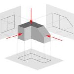
It is important for the fabricator to understand part orientation as it relates to dimensioned geometry. The orthographic projections offer representations as if one were looking directly at a part from various views (Top/Front/Bottom/Right/Left). They are usually shown on a print in rotations of 90deg. These are critical elements of any CNC drawing, as they provide a great deal of information and help limit uncertainty when machining a part.
Sectional Views
On more detailed features, a sectional view can be a useful tool for including additional part dimensions, or for representing internal geometry that may not be viewable in the orthographic projections. Sectionals can also be utilized to zoom in on a particular element that may require further engineering details (tolerances, surface finish, unique geometry, etc.)
Clear Tolerances And Dimensions
A properly dimensioned print is a thing of beauty. It provides the fabricator with all the necessary information to machine a part, without extraneous data that could muddle up a drawing and lead to confusion.
On the flip side, a part that is over-toleranced or missing dimensions will result in production delays and unneeded back and forth between machinists and engineers to clear up inconsistencies or omissions their drawings. Understanding the importance of tolerances and dimensions on a CNC print is critical to ensure success when manufacturing the component.
Know Your Tolerances
Tolerances are essential when dimensioning a part, but they can hinder as much as they can help. Tight tolerances can be critical for certain part features, but if they aren’t necessary, don’t call for them. This will help limit additional time/cost associated with the machining and inspection of a given element.
Stacked tolerances should also be avoided. This refers to scenarios where a number of related features may themselves conform to required dimensions but will fall out of spec when factored together. Tolerances should also be noted only on features that are critical to part function. For other, less essential dimensions, a generic tolerance indicator can be displayed elsewhere on the print.
Provide Clear Dimensions
Dimension what is critical and what can be measured, and avoid the rest. By limiting unnecessary dimensions, you can highlight key part components without detracting from the overall clarity of a print. This also helps fabricators understand the elements of a part that will be most essential to its function.
It is also important to take into account what can and cannot be measured in the field. While the 3D CAD workspace provides engineers with limitless opportunities to dimension their work, it can be far more challenging (and at times impossible) to machine and inspect those elements in the field. Abstract and arbitrary dimensions will bog down even the most sophisticated inspection equipment, so it is always wise to be judicious when choosing which dimensions make it on to a mechanical drawing.
Leave Detailed Notes
Engineering notes can be incredibly helpful in ensuring that a part is made exactly as intended. These could include details on surface finish, deburring/cleaning, secondary processes, material certifications and more. Any miscellaneous requirements that will be expected of a finished part can and should be included. This will help improve the quality of manufacturing and will ensure that all parties are satisfied with the end product.